
intSDX 128kB
The original SDX cartridge contains 64kB of EPROM and is filled up to 99% with software. To add new functions one would have to remove "unnecessary" programs from the CAR: device, which is obviously not a very acceptable solution. Fortunately, thanks to Pasiu, owners of his intSDX (an internal SDX hardware) can easily upgrade it, allowing the use of a 128kB memory chip (there is also a possibility of similar enhancement for the Atrax cartridge). Additional modification, intSDX "flash" designed by jad simplifies the upgrade to subsequent releases of SDX. Section I is the English instruction how to build the 64kB intSDX (for older versions of SDX), while sections II and III contain the instructions how to mod the 64kB intSDX to make it a intSDX 128k for the new SDX.
I. Prerequisite: intSDX with the old SDX 4.22 (64kB)
Note: the following is a short English summary of the information from the
designer's (Pasiu) page.
You can skip this step if you already have intSDX.
Otherwise read all sections I,II,III to get a general idea before making the upgrade.
- Parts needed:
- EPROM 27512 (27c512) programmed with SDX422.zip,
- 28-pin socket (or 32-pin one if you want to be "intSDX 128kB ready", see Sec.II),
- GAL20V8 programmed with SDXv11.jed,
- 74LS175 (74HCT175),
- two 4.7 kohm resistors,
- 1uF capacitor,
- 1N4148 diode,
- a switch.
- The upgrade:
- Solder the socket for the EPROM on top of the OS ROM (28-pin chip on the mainboard), leaving pins 1, 20, 22, 26 i 27 unconnected. Mount the other elements onto an extension board according to this schematics.
- Use the following locations on the mainboard to get the
required signals:
- A4 - Antic (U7) pin 28
- A5 - Antic (U7) pin 27
- A6 - Antic (U7) pin 26
- A7 - Antic (U7) pin 25
- O2 - Antic (U7) pin 29
- R/-W - Antic (U7) pin 14
- CCTL - 74LS138 (HCT138, HCTLS138) (U2) pin 10
- Desolder MMU (U3 - CO61618)
from the mainboard and bend pins 7, 8, 12, 19 up.
Connect the 'to MMU' signals as follows:
- RD4 → MMU pin 7
- RD5 → MMU pin 8
- S4 → MMU pin 19
- S5 → MMU pin 12
- Similarly, connect the 'to cart' signals to the
mainboard soldering holes of the removed MMU:
- RD4 → hole for pin 7
- RD5 → hole for pin 8
- S4 → hole for pin 19
- S5 → hole for pin 12
- Solder the MMU to the mainboard again (leave
the 4 pins bended). Carefully desolder pin 11 from GTIA (U17 - CO14889)
and connect T3 signal to it. Connect power and ground lines (not shown on the
schematics):
- +5V → pin 16 of '175 and pin 24 of GAL
- GND → pin 8 of '175 and pin 12 of GAL.
- Mount the switch on the backside of the computer and test SDX 4.22.
II. intSDX 128kB with the new SDX:
- Parts needed:
- 74LS175 (74HCT175),
- 128kB EPROM (such as 27C010, 29C010 or similar) programmed with the SDX Upgrade rom image,
- 32-pin socket (low profile, precision) for the EPROM chip,
- some wires.
- The upgrade:
- Bend up all pins with the exception of 1,8,9 and 16 on the 74LS175. Cut off the thin part of all bent pins (we are going to use the pins 11 and 12).
- Find the 74LS175 chip already existing in the intSDX and piggy-back the new 74LS175 on top of it (solder pins 1-1, 8-8, 9-9, 16-16).
- Find GAL20V8 in the intSDX and remove the wire leading to pin 8 of this chip. This is the A4 line, usually taken from Antic (it will be used again in pt. 5).
- Connect the pin 8 of the GAL to the ground. To do
this, you can run a wire to the pin 12
of the GAL, already connected to the ground.
- Connect the A4 line (from pt.3) to the bent pin 12 of the new 74LS175.
- Solder pins 30 and 32 of the new socket together (from the bottom side). This is needed for having VCC at pin 32. Don't bend pin 30.
- Run a wire from the bent pin 11 of the new 74LS175 to the pin 2 of the socket (A16).
- Remove the existing 64kB 28-pin chip containing the old SDX and replace it with the new socket (socketed socket ;)) in such a way, that the upper socket (32-pin one) lines up with the old one (28-pin) from the right side (i.e. pin 16), while it sticks out from the other side (pin 1). This is not needed if the old socket is already a 32-pin one.
- Insert the new 128kB EPROM into the socket.
- Turn the computer on. If everything has been properly
done., the SDX will boot up without errors. If something went wrong,
there would be error messages while loading programs from the
additional
EPROM memory space. To see the cartridge directory type DIR CAR:.
- Remarks:
- If you want to use the older Sparta versions (4.20, 4.22), you don't have to disassemble the upgrade - just remove the new 128kB EPROM and insert the old 64kB chip, leaving two empty rows of pins from pin 1 (left) side of the socket (the old chip has 28 pins).
- Instead of putting a socket into another socket you may want to remove the old 28-pin socket and solder in the new 32-pin one (more skills and work required). This has to be done, if the two socket tower would be too high, leaving not enough space for the keyboard. The wires can be soldered directly to the EPROM, but it will disallow any software upgrade.
- The above procedure assumes the standard intSDX. There can be variations of the hardware, such as combined SDX, OS, Basic chip etc. In such a case you are on your own.
- Photo:
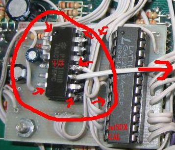
and marked modifications
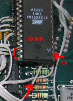
The EPROM connection method
III. intSDX 128 with "flash" option
- Parts needed:
- AT29C010, 29EE010 or 29F010 flash memory
- 4k7 resistor
- switch or jumper.
- The upgrade:
- Remove EPROM if present.
- Connect pins 32 (VCC) and 31 (/WE) of the EPROM socket with the 4k7 resistor.
- Connect pin 31 (/WE) of the socket with R/-W signal (present on pin1 of the intSDX GAL). Install an on/off switch across the connection to allow or prohibit programming the flash memory.
- Program the intSDX GAL with the intSDX_flash.jed.
- Insert the flash memory into the socket
- Use the ATR file to boot the computer and run the SDX flash utility.
Authors:
Pasiu, jad - hardware, DLT - software